Residual Stress – Direct Stress Measuring Method
Overview
Residual stress is the internal stress remaining within a material even in the absence of external forces, which significantly affects the material's strength and fatigue life. Traditional residual stress measurement methods, such as X-ray diffraction, neutron diffraction, and cutting methods using strain gauges, have limitations when applied to complex shapes or small components.
Residual Stress Measurement Using Instrumented Indentation Test (IIT)
Instrumented Indentation Test (IIT) provides a non-destructive method for directly measuring residual stress near the surface, applicable to a wide range of materials and shapes, from nano scale to large structures. Unlike other methods, IIT does not require strain gauges, making it easier to install, and it allows for rapid and flexible measurements on-site, offering greater efficiency than traditional methods.
Residual Stress Measurement Using Instrumented Indentation Test (IIT)
| Type |
Method |
Measuring Parameter |
Measuring Thickness |
Testing Area
(Spatial Resolution) |
Number of Components |
Measurement Effor |
Issues |
| Non-destructive |
XRD |
Lattice Constant |
0.002 ~ 0.5mm |
0.01 ~ 0.5mm² |
In-plane stresses |
Hours |
- · Crystalline materials only
- · Grain size / Texture effect
|
| Synchrotron |
0.1 ~ 100mm |
0.001 ~ 1mm² |
In-plane stresses |
Hours |
| Neutron |
1 ~ 100mm |
0.5mm² |
All stresses |
Hours |
| Ultrasonic |
Wave Velocity |
1 ~ 150mm |
1mm² |
In-plane stresses |
Hours |
- · Microstructural effect
- · Environmental effect(temperature)
|
| Destructive |
Hole drilling |
Surface Strain |
0.2 ~ 2mm |
0.5mm² |
In-plane stresses |
Hours |
- · Low spatial resolution
- · Plasticity during machining
|
| RIng-core |
5 ~20mm |
Hours |
| Deep-HD |
1 ~ mm |
5mm² |
In-plane stresses |
Days |
| Sectioning |
5mm² |
Normal stresses |
Days |
| Sitting |
0.5mm² |
Normal stresses |
Hours |
| Contour |
0.01~1mm² |
Normal stresses |
Days |
- · Uncertainty at near surface
- · Plasticity during machining
|
Residual Stress Measurement Using Instrumented Indentation Test (IIT)
| Type |
Method |
Measuring Parameter |
Measuring Thickness |
Testing Area
(Spatial Resolution) |
Number of Components |
Measurement Effort |
Merits |
| Semi-destructive |
Instrumented Indentation Test |
Indentation Load
(Strain measu rement X) |
0.0001 ~ mm |
0.0000001 ~ 1mm² |
In-plane stresses |
Minutes |
- · Quick test (<30 sec/point)
- · Near surface measurement
- · Direct stress measuring technique
- · High in-field applicability
- · Applicable to a variety of materials
- · Unaffected by microstructure
|
Basic Principle of Residual Stress Measurement
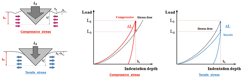
Figure 1 illustrates the effect of residual stress on the load-displacement curve. When compressive residual stress is present, a higher load is required, while tensile residual stress requires a lower load. In IIT, residual stress is quantitatively evaluated by comparing the load-displacement curves for cases with and without residual stress.
Figure 1. Basic Principle of Residual Stress Measurement
In Figure 1, L0 represents the load at the hS point under no stress, and LS represents the load at the hS point under stress conditions. The difference (∆L) between these values is related to surface residual stress and is addressed as a standard in ISO TS 19096.
Advantages of the Instrumented Indentation Test (IIT)
Direct Stress Measurement:
IIT directly measures surface stress by analyzing the indentation load-depth curve.
Consistent Accuracy
The effects of microstructure and environmental factors are minimal, and the procedure is simple, ensuring consistent results.
Convenient Stress Difference Analysis
Since a stress-free state is not required, it is easy to evaluate stress changes by comparing indentation load-displacement curves.
Non-Destructive Evaluation
Residual stress can be measured without damaging the material, preserving its structure after testing.
Wide Applicability
IIT is highly versatile, applicable to metals, amorphous materials, polymers, and other materials, making it widely used in industrial applications.
Comparison of IIT with Other Methods
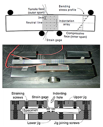
To ensure the accuracy of stress measurements obtained through IIT, a validation methodology was implemented, comparing IIT results with a predetermined benchmark stress level in the same material. A specimen made of SA-508 Gr. 1A was subjected to controlled bending within its elastic deformation range to induce stress, which was accurately measured using strain gauges, as shown in Figure 2. IIT was then conducted using AIS equipment along the specimen's central line, allowing for a direct comparison between the measured stress and the benchmark stress during the application of elastic bending stress.
Figure 2. Illustration of the experimental setup using a 4-point bending jig to apply stress to a specimen of SA-508Gr.1A.
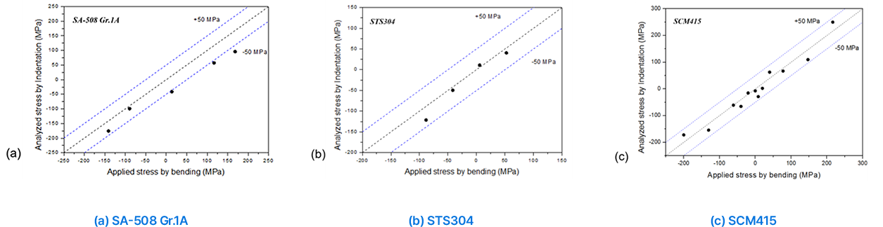
Figure 3. Comparative analysis of IIT-measured stress values with known elastic bending stress. (a) SA-508 Gr.1A (b) STS304 (c) SCM415
Figure 3(a) shows the close correlation between the measured and expected stress levels, exhibiting minimal deviation of less than50 MPa across the entire stress range. Furthermore, Figure 3(b) and (c) present additional materials tests (STS 304 and SCM 415), where IIT consistently aligns with the known bending stress, emphasizing the technique's reliability and precision. /p>
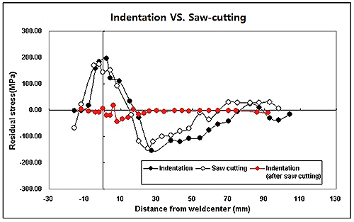
Figure 4 shows a comparison of residual stress measurements on welded specimens using IIT and the saw-cut method, where similar trends were observed between the two methods. The stress was removed from the specimen after cutting, as indicated by the red color.
Figure 4. Comparison of Residual Stress Measured using IIT and theSaw-Cut Method
 Directions